Hardware#
Overview#
The following pages introduce key components, concepts and aspects of any UltraZohm system:
As of 2025, there are two “major versions” of UltraZohm systems in existence:
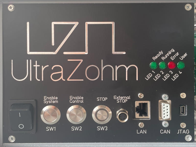
Systems based on carrier boards ≤ Rev04, where
system power is controlled by a “0/1” power switch on the front panel,
power supply and 230V inlet are located on the SoM (i.e., when looking from the front, left-hand) side of the chassis, and
the front panel consists of several individual components (e.g., a dedicated cable harness per Ethernet, USB, and CAN connector).
Please refer to the left-hand side of Comparison of front panels across carrier board revisions (photos) if you are unsure about the revision :)
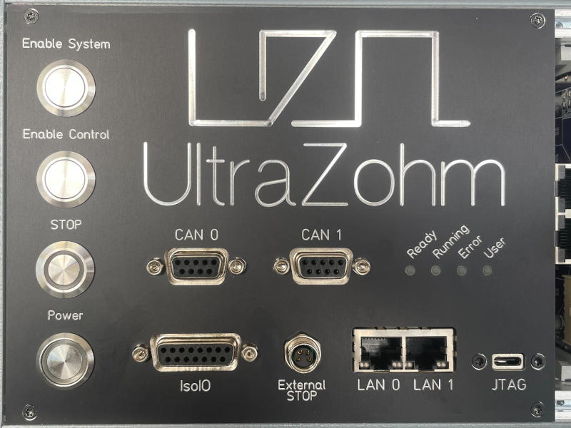
Systems based on carrier boards ≥ Rev05, where
system power is controlled by a power button on the front panel (and a 230V switch on the back panel, cf. “What’s different?” for Rev04 Users and System Supply & Safety Component (S3C)),
power supply and 230V inlet are located on the adapter card (i.e., when looking from the front, right-hand) side of the chassis, and
the front panel consists of three interconnected PCBs, most notably the Front Panel Mainboard (which links the entire assembly to the carrier).
Please refer to the right-hand side of Comparison of front panels across carrier board revisions (photos) if you are unsure about the revision :)
Front panel for ≤Rev04 carriers |
Front panel for ≥Rev05 carriers |
|---|---|
|
|
Adapter Cards#
Analog Cards
Additional Components#
External
Internal
Deskbench