Create a CPLD program using Lattice Diamond#
The main goal of this section is to describe the necessary steps for creating a simple program for the
MACHXO2 CPLDs on the UltraZohm \(\geq\) Rev05.
All signals from the FPGA to the digital adapter cards pass through the CPLDs.
D-Slot CPLDs#
Everything is programmed inside the project uz_d_slots.ldf.
It is located in the repository at MACHXO2/D_Slot_CPLD_LCMXO2-2000HC-4TG100C/uz_d_slots/.
Here we can create additional implementations for the CPLD.
The advantage of having all CPLD programs within one project is that VHDL code from other files can be used, but every file has its constraints (e.g., all signals function as inputs versus all signals function as outputs).
Step-by-step#
Open Lattice Diamond and there the project
uz_d_slots.ldf. ClickOpen.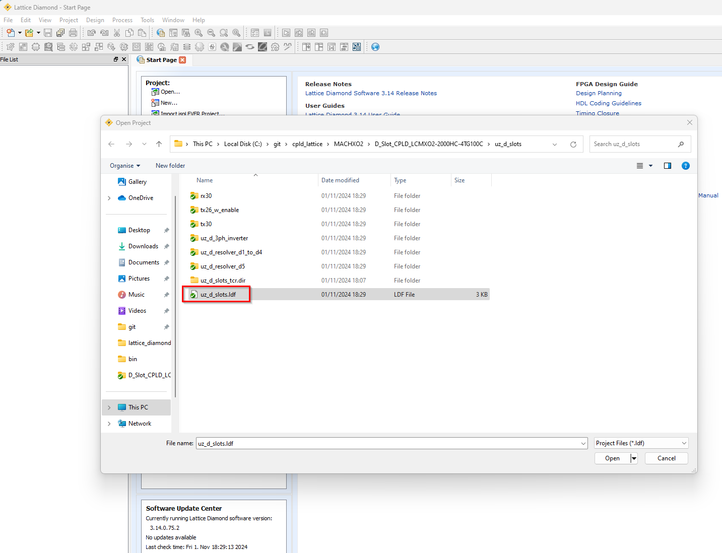
For creating a new CPLD program, click
Clone Implementationby right-clicking on the templatetemplate_dslotsand the subsequent context menu.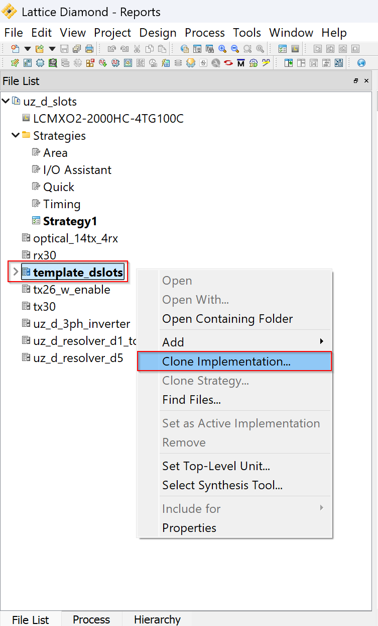
Provide a proper
Nameand give theDirectorythe same name. Select theDefault Strategyto Strategy1 and check the boxCopy files into new implementation source directory. ClickOK.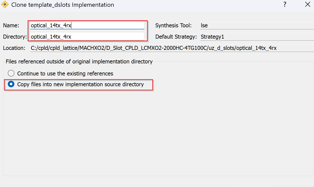
To modify the new implementation, right-click on it and
Set as Active Implementation.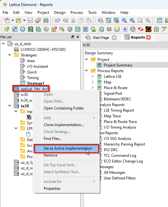
The template
VHDL Fileis copied to the source directory. Remove it by right-clicking theInputFileandRemove.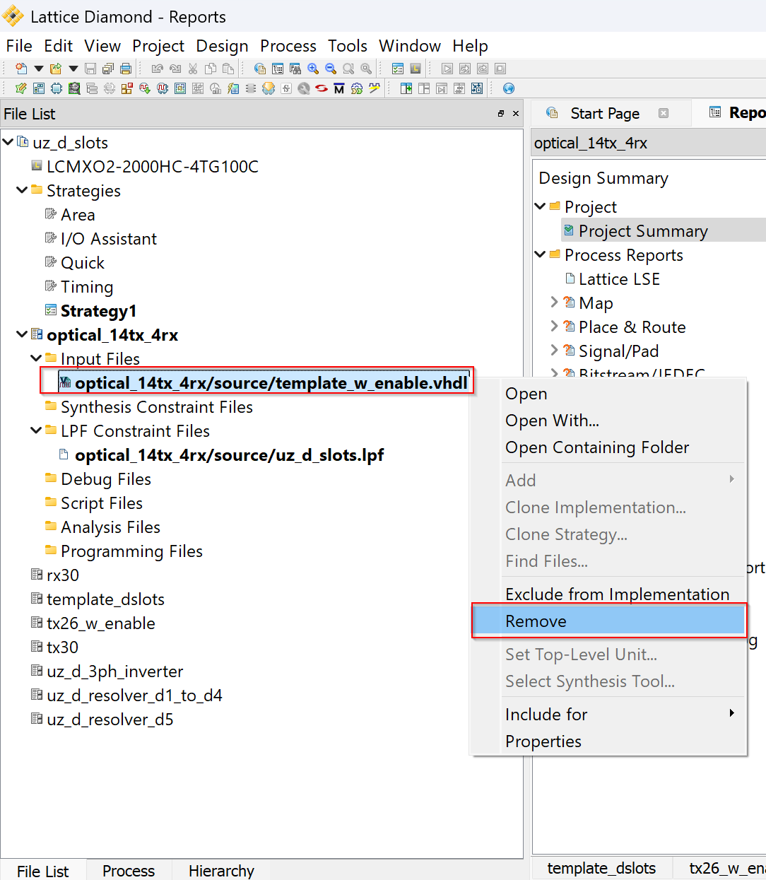
Right-click the project file and
Open Containing Folder.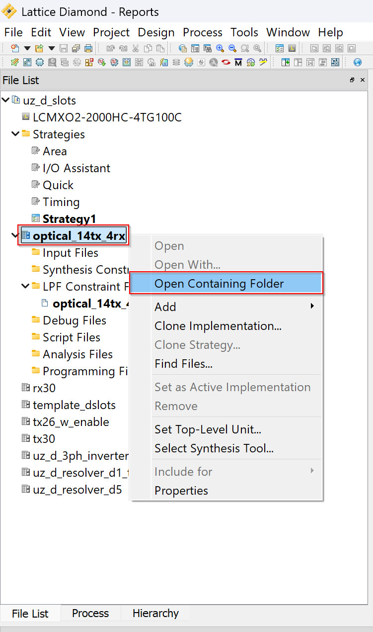
Edit the template
VHDL Fileand name it according to your project.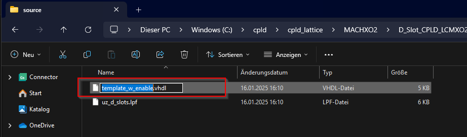
Add the renamed
VHDL Fileto your project by right-clicking theInputFiles-Add-Existing File.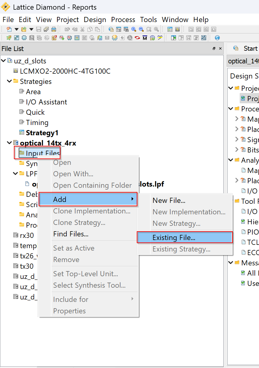
Set
Files of type:toAll Files, navigate to your source directory and add your previously renamedVHDL File.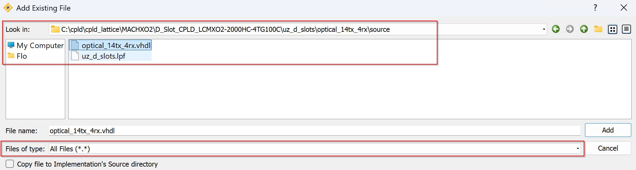
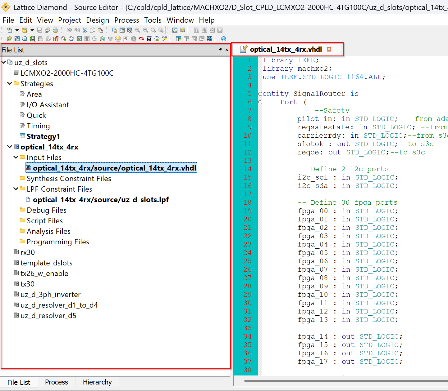
Write VHDL code for the CPLD and save it.
Note
The table in Functions shows the dedicated wiring between the S3C and the D-Slot CPLDs. In the accompanying VHDL snippet, the default setting keeps the forwarding from SoM to card permanently enabled:
user_enable_forwarding <= '1';
--user_enable_forwarding <= '1' when (fpga_26 = '0' AND fpga_27 = '0' AND  fpga_28 = '1' AND fpga_29 = '1') else '0';
The commented line underneath illustrates an alternative scheme in which the FPGA drives a specific pin pattern (0011) to turn forwarding on or off (already known as
..._w(ith)_enablefrom the old LC4xxx CPLDs). The user can freely adapt or expand that logic to suit any custom forwarding rules. Note that this “user-enable” path is later OR-ed with the reqsafestate signal – forced low by the S3C during regular operation – and the resulting value feeds the enable_forwarding net. In other words, forwarding is active only when both the (per-slot) user permission and the (system-wide) S3C safety request allow it.--Fixed definitions reqoe <= NOT tristate_outputs; enable_forwarding <= user_enable_forwarding AND NOT reqsafestate; -- Specific safety definitions for card slotok <= enable_forwarding; -- tristate_outputs <= NOT pilot_in; -- set to pilot_in if card is driven by pilot_in, definition can be extended by user based on card-specific logic AND internal states tristate_outputs <= '0'; -- Define the user-specific enable_forwarding signal logic user_enable_forwarding <= '1'; -- for tx30 --user_enable_forwarding <= '1' when (fpga_26 = '0' AND fpga_27 = '0' AND fpga_28 = '1' AND fpga_29 = '1') else '0'; -- for tx26_w_enable
Note
Example for I/O
-- Input Port Example
fpga_00 <=  d_00; -- This port is an input

-- Output Port Example
d_00 <= fpga_00 AND enable_forwarding; -- This port is an output
There is no dedicated enable logic between the S3C and the D-Slot CPLD for input signals. From the system’s standpoint, signal validity should be handled by the SoM, so – rather than adding complexity – the signal is simply forwarded unchanged through every instance.
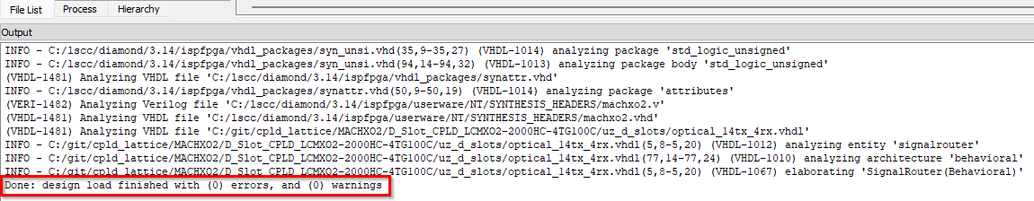
When saving, Diamond automatically checks the code and gives feedback. If everything is fine, it looks as below.
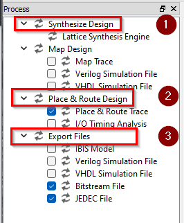
Switch to the
Processview.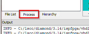
Start the processes shown below by double-clicking on them, one after another.
If every process passed, it looks as shown below. You can now use the exported
JEDEC Fileto flash a CPLD with the Diamond Programmer as per Programming the CPLD.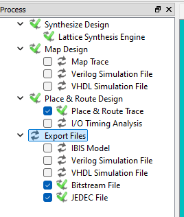
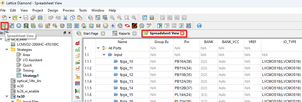
15. Constraints for the D-Slot CPLDs are provided in the existing uz_d_slots.ldf project. If ever needed, one can check and modify the
constraints by opening the Spreadsheet View.
S3C#
The same procedure can be applied to create a program for the S3C.
Everything is programmed inside the project UZ_Rev05_S3C.ldf.
It is located in the repository at MACHXO2/S3C_CPLD_LCMXO2-4000HC-4TG144C/.
Danger
Modifying the bitstream of the S3C fundamentally alters the startup and power-down behavior of the UZ. Such changes may render the carrier board inoperative, requiring physical recovery through soldering. Exercise caution in your actions within this context.
Note
Check the schematic from the Carrierboard to see which signals are inputs, outputs, open-drain or bidirectional. The pins have a dedicated direction and cannot be freely configured.