Default Vivado project#
The default Vivado project uses vendor IP cores as well as IP cores from the UltraZohm repository (IP Cores) to provide a starting point for users.
It is located in ultrazohm_sw/vivado/project/ultrazohm.xpr and can be generated using the build.tcl script (see Vivado build Tcl scripts).
Fig. 65 shows the default project.
It is split into the following different parts:
Input ports from the digital and analog adapter cards
The processing system (PS) with R5 and A53.
uz_systemwith clocks, interrupts, AXI infrastructure, and IP cores for system functions.The IP cores to interface the adapter cards on A1, A2, and A3.
The output ports to digital and analog adapter cards.
The
uz_usersubsystem where user-specific IP cores should be placed.The IP cores to interface the digital adapter cards on D1, D2, D3, D4, and D5.
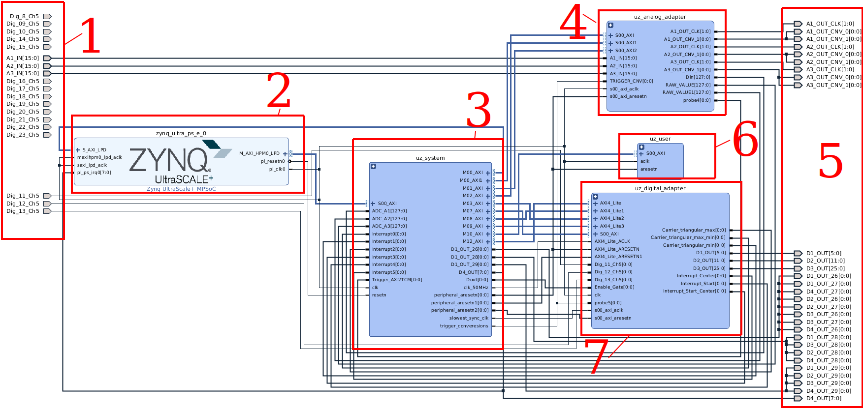
Fig. 65 Default Vivado project of the UltraZohm. Add custom IP cores to uz_user sub-block.#
The sub-blocks (Create hierarchy in Vivado) provide the following functionality:
- uz_system
smartconnect_0 to connect AXI signals to the PS
uz_enable handles enabling the output signals as well as the data mover
uz_clocks generates 100 MHz, 50 MHz, 10 MHz clocks for IP cores and matching reset signals
timer_update_64bit is the counter used for System Time R5
Data Mover / AXI2TCM transfers data from PL to PS
Interrupt controls the interrupts of the R5 in the PL (R5 interrupts)
- uz_user
AXI Test IP to use in How to create an IP core driver and to test AXI communication
Custom IP cores that are specific to a user project should be added in this sub-block
- uz_analog_adapter
A1: Analog LTC2311-16 3v01 IP core, IOBUF, and inversion constant (see Compatibility with TE0803) for Analog LTC2311-16 3v01 (v3 and higher) adapter card
A2: Analog LTC2311-16 3v01 IP core, IOBUF, and inversion constant (see Compatibility with TE0803) for Analog LTC2311-16 3v01 (v3 and higher) adapter card
A3: Analog LTC2311-16 3v01 IP core, IOBUF, and inversion constant (see Compatibility with TE0803) for Analog LTC2311-16 3v01 (v3 and higher) adapter card
- uz_digital_adapter
D1: PWM and SS Control V4 and Interlock and Deadtime module (2L) IP core (adapter card agnostic, e.g., Digital Voltage 3U 2v01 or Digital Optical)
D2: PWM module and interlock for three level inverter (adapter card agnostic, e.g., Digital Voltage 3U 2v01 or Digital Optical)
D3: VIO for Virtual Input Output (VIO)
D4: not connected, interrupt signals are directly routed to D4[7:0]
D5: Incremental Encoder IP core for Digital Incremental Encoder adapter card