Wolfspeed Inverter 2L 25 kW Interface Rev03#
Rev03 is the first productive revision of the uz_per_wolfspeed_25kw_FM3 interface PCB.
It interfaces the UltraZohm with the Wolfspeed CRD25DA12N-FMC inverter by replacing the original control card.
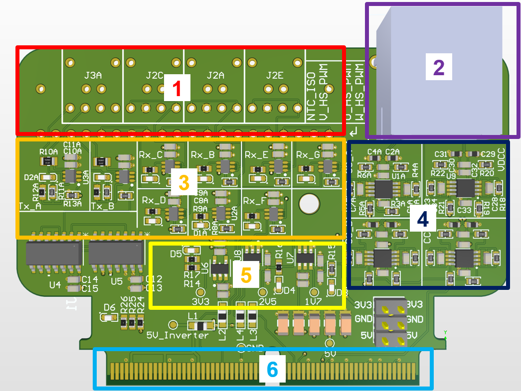
Fig. 303 Functional areas of the Rev03 interface PCB#
Layout#
The PCB is structured by functional areas as shown in Functional areas of the Rev03 interface PCB.
HFBR-1521Z/2521Z digital optical transmitters and receivers
RJ45 port for analog signal transmission
Driver stages for the optical links
TI THS4561 fully differential amplifier stages
Power section with TPS7A20 3.3 V LDO and REF35 voltage references
Samtec HSEC8 120-pin edge-card connector mating with the Wolfspeed inverter
Analog Signals#
The inverter-side analog signals are single-ended and are converted to fully differential signals for noise-robust transmission to the UltraZohm ADC board.
The interface scales the single-ended signals by a factor of 1.5038 (10 / 6.65) to match the inverter-side 3.3 V analog range to the 5 V input range of the UltraZohm ADC board.
The reported total sensing gain was measured experimentally and includes both the inverter-side measurement device and the interface board. The bandwidth was determined theoretically from LTSpice simulations.
Signal |
Source |
Total measurement gain |
UltraZohm ADC channel |
|---|---|---|---|
Phase current U |
LEM LAH 50-P |
0.02417 V/A, bandwidth about 50 kHz |
|
Phase current V |
LEM LAH 50-P |
0.02417 V/A, bandwidth about 50 kHz |
|
Phase current W |
LEM LAH 50-P |
0.02417 V/A, bandwidth about 50 kHz |
|
DC-link voltage |
Non-isolated voltage divider |
0.003744 Vsec/Vprim, bandwidth about 7 kHz |
|
Digital Signals#
Rev03 uses optical receivers for the UltraZohm-to-inverter PWM and gate-disable signals. The inverter-to-UltraZohm overcurrent and temperature signals use optical transmitters.
The overcurrent detection signal is active low.
When an overcurrent event is detected, the signal goes low and the transmitter LED is off.
The default Wolfspeed overcurrent limits are set to approximately +/-79 A and can be adjusted with the reference resistors described in the Wolfspeed documentation.
Signal |
Direction |
Conditioning |
Notes |
|---|---|---|---|
|
UltraZohm to inverter |
Optical receivers |
High-side and low-side PWM for three phases; dead time is generated in the UltraZohm. |
|
UltraZohm to inverter |
Optical receiver |
Global gate-driver disable signal. |
|
Inverter to UltraZohm |
SN74HCS08DR AND logic and optical transmitter |
Consolidated overcurrent signal from six comparator outputs. |
|
Inverter to UltraZohm |
Optical transmitter |
Inverter-side temperature signal forwarded as a digital optical signal. |
Testing#
Rev03 was tested up to 10 kW with an RL load consisting of a 14 Ohm resistor and a 1 mH inductor.
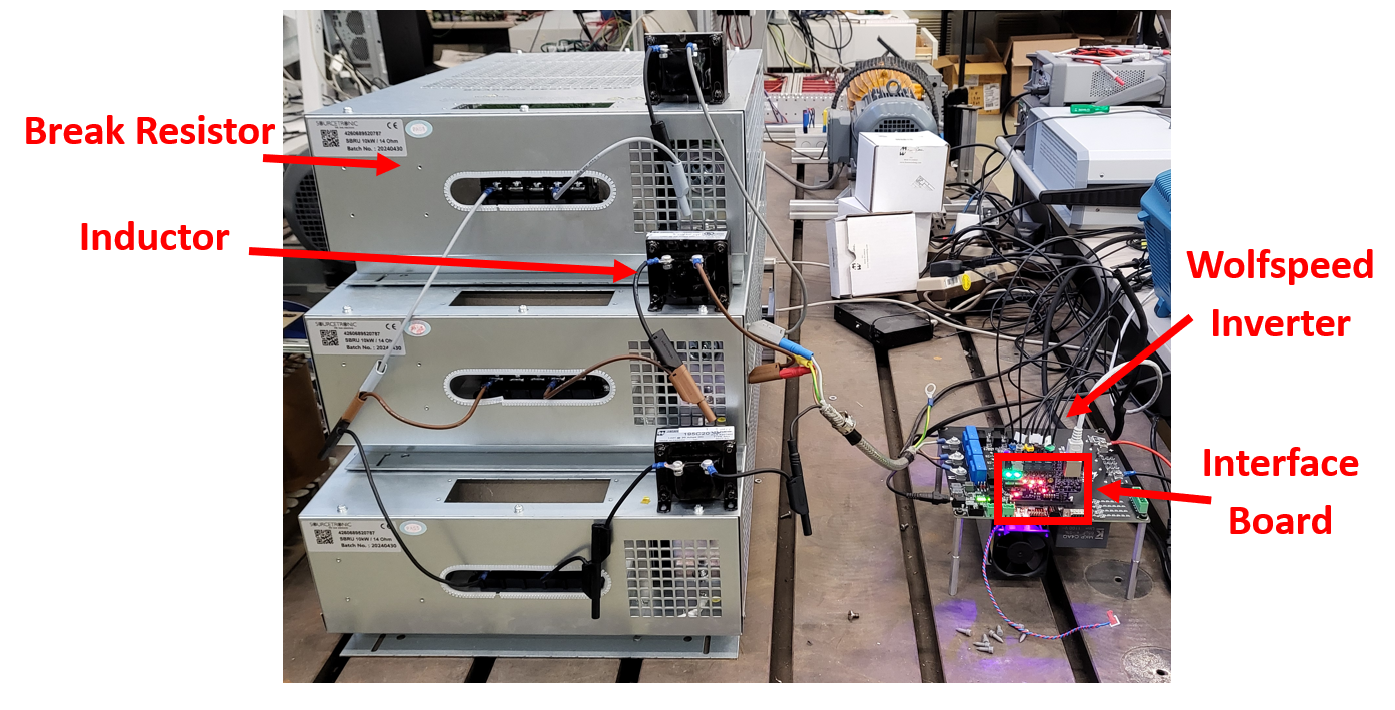
Fig. 304 Integrated testing setup with RL load#
Stable three-phase sinusoidal currents were measured using a Rohde & Schwarz MXO 5 series oscilloscope.
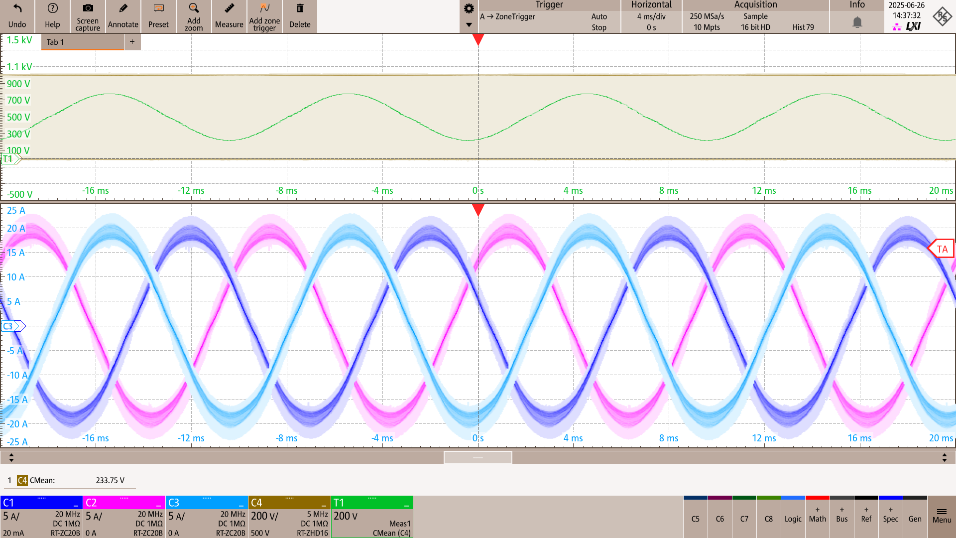
Fig. 305 Oscilloscope measurement at 100 kHz switching frequency with a 999 V / 8.33 A DC-link input#
Mechanical Support#
A 3D-printed support stand was added to keep the board mechanically stable when plugged into the inverter. The step file of the stand is available in the PCB repository.
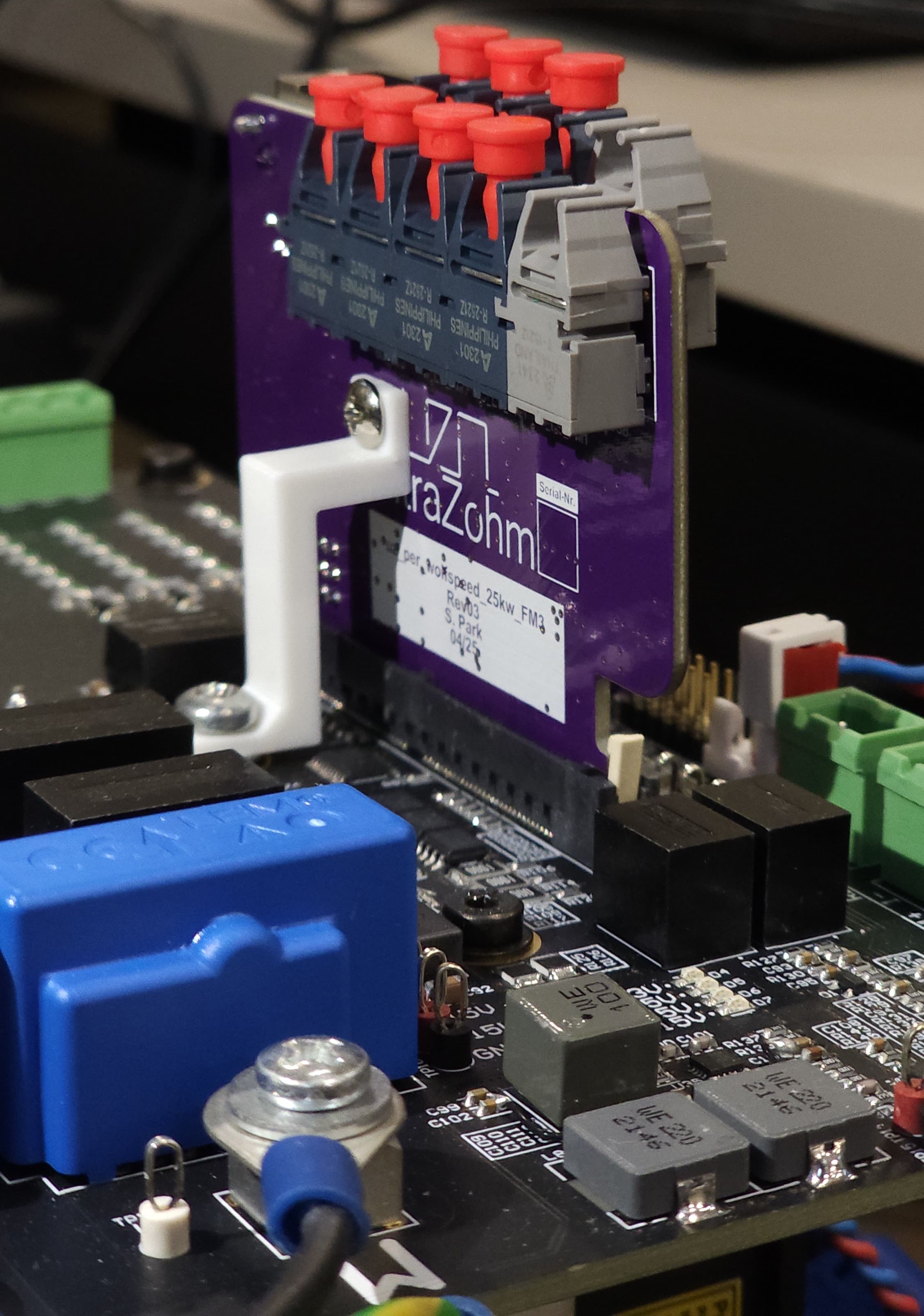
Fig. 306 Interface board with 3D-printed stand for mechanical stability#
Software Used for Testing#
The inverter was tested with the feature/wolfspeed_inverter_adapterboard branch of the ultrazohm_sw repository.
The branch comparison is available here.